 DIY mmWave Radar Near-Field Imaging Platform
Overview
This project presents a DIY millimeter-wave radar near-field imaging system built from scratch using a custom 2D linear rail platform. By integrating GRBL motion control with radar data acquisition and imaging algorithms into a single compact program, the system achieves vendor-independent operation and rapid prototyping capabilities.
Honest Assessment: While the imaging quality is admittedly subpar due to open-loop motor control and rapid scanning causing step loss, this project served as a valuable learning experience in radar imaging principles and mechatronic system integration.
System Architecture
Hardware Platform
2D Linear Rail System
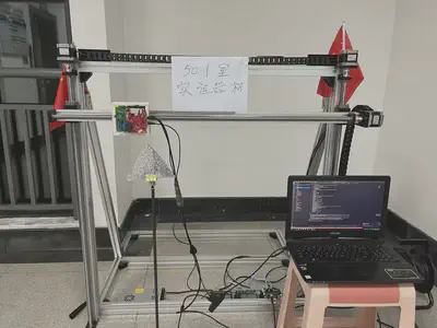
The mechanical platform consists of:
- X-Y Linear Rails: Custom-built 2D scanning mechanism
- Stepper Motors: NEMA 17 stepper motors for both axes
- GRBL Controller: GRBL-based motion control board
- mmWave Radar: Mounted on the moving platform for scanning
- Frame Structure: Aluminum extrusion frame for rigidity
Motion Control System
GRBL-Based Control
- Open-Loop Stepper Control: Cost-effective but prone to step loss
- G-Code Commands: Standard CNC control protocol
- USB Serial Interface: Direct PC communication
- Configurable Speed: Adjustable scanning speed (trade-off: speed vs. accuracy)
Key Limitation: The use of open-loop stepper motors without position feedback means:
- ⚠️ Rapid scanning can cause step loss
- ⚠️ No error correction for missed steps
- ⚠️ Position accuracy degrades over time
- ⚠️ Vibration and acceleration affect precision
Software Integration
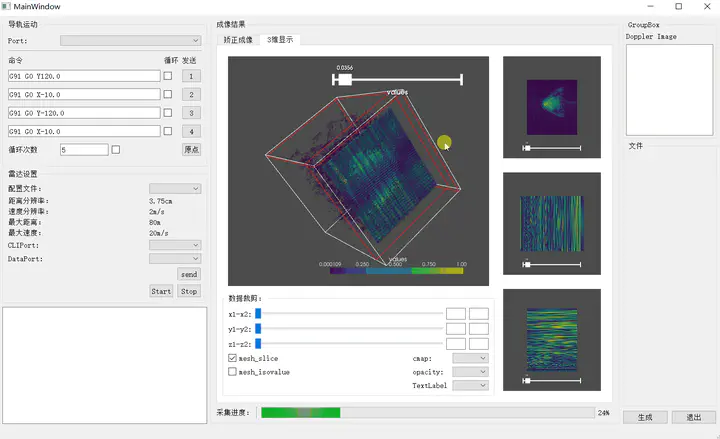
All-in-One Program
One of the key advantages of this DIY approach is vendor independence. Unlike commercial systems requiring proprietary software, this system integrates everything into a single lightweight program.
Benefits:
- ✅ No dependency on vendor-specific software
- ✅ Easy to modify and experiment
- ✅ Lightweight and fast
- ✅ Complete control over scanning patterns
- ✅ Integrated data processing pipeline
Imaging Algorithm
Near-Field SAR Processing
- Data Collection: Radar samples at each grid point
- Range Profile Extraction: FFT processing of raw radar data
- Spatial Sampling: 2D grid scanning pattern
- Back-Projection Algorithm: Coherent summation for image formation
- Image Reconstruction: 2D/3D visualization of targets
Implemented Algorithms:
- Range-Doppler processing
- Back-projection imaging
- Frequency-domain focusing
- Basic clutter suppression
Experimental Results
Imaging Performance
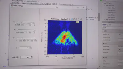
Honest Assessment
Image Quality: ⭐⭐☆☆☆ (Poor to Fair)
The imaging results are admittedly subpar due to several factors:
Root Causes of Poor Quality:
-
Open-Loop Control 🔴
- No position feedback
- Accumulated positioning errors
- Step loss during rapid movements
-
Speed vs. Accuracy Trade-off 🔴
- Prioritized fast scanning (to reduce total scan time)
- High acceleration causes mechanical vibration
- Insufficient settling time at each position
-
Mechanical Limitations 🟡
- Frame rigidity not optimal
- Backlash in linear rail system
- Motor vibration during movement
-
Limited Calibration 🟡
- Basic calibration only
- No real-time position verification
- Environmental factors not compensated
What Worked
Despite the limitations, the system successfully demonstrated:
- ✅ Basic near-field imaging capability
- ✅ Automated 2D scanning
- ✅ Real-time data acquisition and processing
- ✅ Vendor-independent operation
- ✅ Rapid prototyping and experimentation
Lessons Learned
This project provided valuable insights into radar imaging systems:
Technical Insights
-
Position Accuracy is Critical 🎯
- Imaging quality is directly tied to positioning precision
- Open-loop control is insufficient for high-quality imaging
- Sub-millimeter accuracy needed for good results
-
Speed-Accuracy Trade-off ⚖️
- Faster scanning reduces total time but degrades quality
- Need to balance throughput with positioning accuracy
- Acceleration profiles matter significantly
-
System Integration Complexity 🔧
- Synchronizing motion and data acquisition is challenging
- Timing jitter affects image quality
- Need robust error handling
-
DIY Advantages 💡
- Complete control over system parameters
- Easy to experiment with different algorithms
- Low cost for learning and prototyping
- No vendor lock-in
Future Improvements
Next-Generation Platform (Planned) 🚀
I plan to build an improved desktop-scale imaging platform with:
Mechanical Upgrades
- CoreXY Structure 🔄
- Better speed and acceleration
- Reduced moving mass
- Improved positioning accuracy
- Smoother motion profiles
Motion Control Upgrades
- Closed-Loop Stepper Motors 🔁
- Real-time position feedback
- Automatic error correction
- Stall detection and recovery
- Precise position verification
Radar Upgrades
- Custom DIY Mini Radar Board 📡
- Compact form factor
- Optimized for near-field imaging
- Better integration with platform
- Lower cost and higher flexibility
Software Enhancements
- Advanced imaging algorithms (RMA, Omega-K)
- Real-time autofocus
- Motion compensation
- Enhanced visualization
Expected Improvements
With these upgrades, the next version should achieve:
- 📈 10x better positioning accuracy (closed-loop control)
- 📈 5x faster scanning (CoreXY kinematics)
- 📈 Significantly improved image quality (better hardware + algorithms)
- 📈 More reliable operation (error detection and correction)
Stay Tuned! 🎬
The next-generation platform is in the planning stages. Follow this space for updates on the improved desktop mmWave imaging system!
Applications
Despite current limitations, near-field radar imaging has promising applications:
- 🔍 Non-Destructive Testing: Detecting defects in materials
- 📦 Security Screening: Concealed object detection
- 🏥 Medical Imaging: Complementary to other modalities
- 🔬 Research & Education: Learning radar imaging principles
- 🛠️ Prototyping: Testing imaging algorithms
Technical Specifications
Current System
| Component | Specification |
|---|---|
| Scanning Area | 300mm × 300mm |
| Position Resolution | ~1mm (theoretical, degraded in practice) |
| Scanning Speed | 50-100 mm/s |
| Radar Frequency | 77 GHz (mmWave) |
| Range Resolution | ~5 cm |
| Total Scan Time | 5-10 minutes (full area) |
| Control Interface | USB Serial (GRBL) |
| Software | Custom Python/C++ program |
Conclusion: This project represents an honest exploration of DIY radar imaging. While the results fell short of commercial systems, the learning experience and system integration knowledge gained were invaluable. The next iteration will address the identified shortcomings with better hardware and control strategies.
Qin Chen 陈钦
Ph.D of Information and Communication Engineering
My research interests include Human-computer interaction, signal processing and machine learning.